Reverse Engineered Easel: PROGRESS I


Out of the options I considered in my last blogpost, I decided to reverse engineer the easel via 3D modelling in Rhino 7. In preparation for the 3D modelling, I decided to count, label, and sketch all the metal/plastic components and wheels. I will begin designing those forms because they are most challenging parts for this project.


1) Disassembling & sketching all the metal/plastic components


I roughly sketched each metal/plastic component and kept track of its location by placing their labels on the image to the left. I gave each type of component a letter from A-K and colour coded them for clarity. 

I also kept track of how many times each figure is repeated in the model.

I noticed that each piece of wood already has a little label with a number on it, so I will count them all and organize them on a similar chart. 

2) Selecting the first component to model


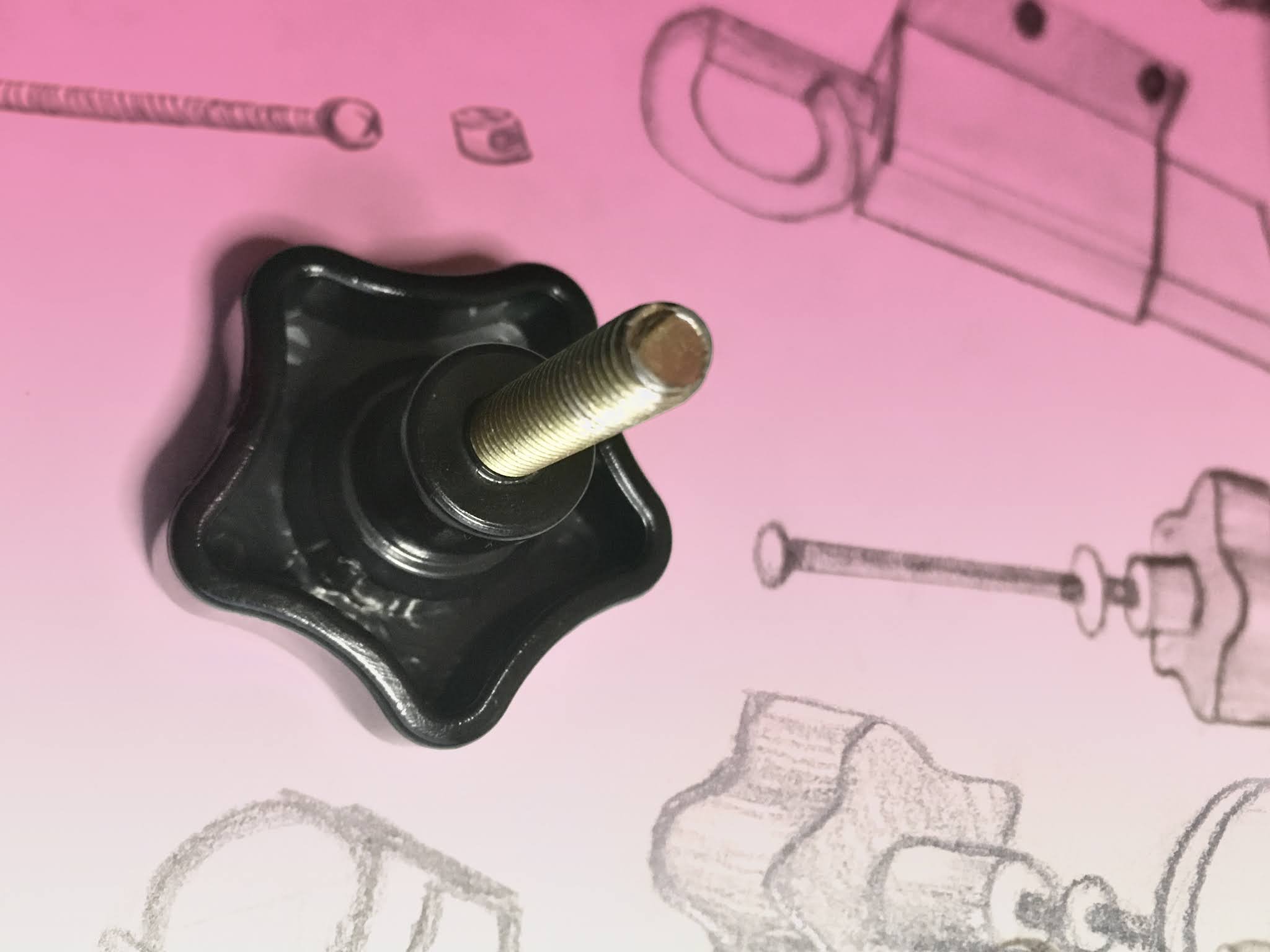
I am starting off with modelling "J," which is the screw and metal piece. The screw is used to loosen the top holder of the easel and change its position. The position of this piece is regulated depending on the height of the canvas or paper being held.

3) Measuring and modelling components


For many years, I've had a very decent Skill Tech dial caliper. At the start of this project, I predicted that it wasn't the ideal tool because it takes me a long time to make sure that each measurement is correct. So, a few weeks ago, I investigated different types of digital calipers online. I decided to buy the iGaging caliper which had good reviews and would make the measuring process easier. However, there was a problem with the order and it has not arrived yet. So, I am trying to make the dial caliper work for now. 


I modelled and rendered the little metal piece, which is what the big screw presses up against to keep the whole wooden section in place. I'm sure this component has a name but I can't figure it out. The two thin pieces that extend from the sides have a slight edge fillet. This is because the original piece was a continuous piece of metal (including the two arms) and it was likely bent into its shape.


Top view photo of the screw head
I also started to reverse engineer one of the screws. Initially, I started with the plastic head because I thought it would be simpler than the metal screw part. Though the original form and my modelling process look simple, it took time to get the right starting shape. I redrew the form about 7 times before I could match the curves and proportions of the outer perimeter.

To create a seamless transition between the curves, I used the tangent circle tool. Initially, the reference points on the circle were located at the quads but it made a very steep curve. So, I placed the reference points higher up on the circles to create a shallower slope.

Since the plastic screw head has a curve, I am not sure how to extrude my 2D outline. I guess that I might have to use the network surface command? 
If so, that would be exciting because I didn't expect to use it for this project.

I also predict that I will have to use the fillet edge command on all the edges after I create the solid object. 

Since I have a lot of questions about recreating the plastic head, I decided to stop working on it until I can ask Bryan in class.


Uncapped spiral extrusion
Since I was a little unsure about how to proceed with the plastic head, I began to model the screw. I found this part challenging because it had been many days since we learned how to do it in class. My memory failed me when it came time to boolean union the twisting extrusion with the interior cylinder. I forgot that I needed to cap the twisted extrusion to join it with the cylinder. I was trying to figure it out for about 15 minutes until I remembered Bryan telling us to cap our spirals. 

I am really glad I did the screw this week because if I would have waited longer I might have forgotten this tip. 

Also, I am glad I did it because the shiny gold render makes me very happy :)

4) Thoughts and plans

Overall, I feel like I made a good start to the project. The parts that I started with allowed me to brush up on my 3D Rhino skillsI have been mostly doing 2D lately. I also started with the flat screw which is nice because it is incorporated in many of the components. I made the screw extra long so that I can cut it to different lengths for the other parts.

Depending on how long it takes me to do the entire easel model, I may or may not animate the exploded model. I started researching what software/methods would work best for my project and experience level. I haven't done an in-depth investigation yet but it seems that Blender would be a good option. 

A YouTube channel called Interfluo, made this video with shows a basic way to animate assemblies in Blender. The video gives me a good idea of how to do the animation but it doesn't show how to render the objects realistically. I don't have experience with Blender, so I would have to learn how to create realistic materials and light setups. I will probably research this if I finish modelling the easel early. I am very excited with this project!

Until my next blogpost :)

Comments

Popular Posts